Technical Details
- Stroke length: 15 mm (HP2a, HP3a), 20 mm (HP4a)
- Rod force: 2000 N (HP2a), 4200 N (HP3a), 5800 N (HP4a)
- Stroke volume adjustment range: 0 – 100%
- Stroke volume adjustment: manually using scaled rotary dial (optionally with electric actuator or control drive)
- The dosing precision is better than ± 1 % within the 20 to 100% stroke volume range under defined conditions and with correct installation
- PTFE multi-layer diaphragm with electrical diaphragm rupture warning / signalling system via a contact
- Integrated hydraulic relief and vent valve
- Wetted materials: PVDF, PTFE+25% carbon, stainless steel 1.4571, Hastelloy C.
- A wide range of power end/drive versions is available: Three-phase or 1-phase AC motor, motors for use in areas at risk from explosion, different flange designs for use of customer-specific motors
- Degree of protection: IP 55
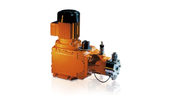
Hydraulic Diaphragm Metering Pump HYDRO HP2a
Technical data for HYDRO HP2a
| Type |
Capacity at max. back pressure with 1500 rpm motor at 50 Hz |
Capacity at max. back pressure at 60 Hz |
Suction lift |
Perm. pre-pressure suction side |
Suction/discharge side connector |
Shipping weight |
Plunger Ø |
|
|
Max. stroke rate |
|
Max. stroke rate |
|
|
|
|
|
|
l/h |
bar |
ml/stroke |
Strokes/min |
psi |
l/h / gph (US) |
Strokes/min |
m WC |
bar |
G-DN |
kg |
mm |
| * SST version with double ball valve, valve connector on the suction-discharge side with female thread Rp 1/4 and male thread G 3/4 – DN 10 |
| ** HV design with G1 – DN 15 connector |
| 100003 * |
3 |
100 |
3.0 |
60 |
1,450 |
3.6/1.0 |
72 |
3.0 |
5 |
Rp 1/4 |
31 |
16 |
| 100006 * |
6 |
100 |
3.0 |
125 |
1,450 |
7.0/1.8 |
150 |
3.0 |
5 |
Rp 1/4 |
31 |
16 |
| 100007 * |
7 |
100 |
3.0 |
150 |
1,450 |
8.0/2.1 |
180 |
3.0 |
5 |
Rp 1/4 |
31 |
16 |
| 100009 * |
9 |
100 |
3.0 |
187 |
1,450 |
11.0/2.9 |
224 |
3.0 |
5 |
Rp 1/4 |
31 |
16 |
| 100010 * |
10 |
100 |
3.0 |
212 |
– |
– |
– |
3.0 |
5 |
Rp 1/4 |
31 |
16 |
| 064007 |
7 |
64 |
3.8 |
60 |
928 |
8.4/2.2 |
72 |
3.0 |
5 |
G 3/4-10 |
31 |
18 |
| 064015 |
15 |
64 |
3.8 |
125 |
928 |
18.0/4.8 |
150 |
3.0 |
5 |
G 3/4-10 |
31 |
18 |
| 064018 |
18 |
64 |
3.8 |
150 |
928 |
21.0/5.5 |
180 |
3.0 |
5 |
G 3/4-10 |
31 |
18 |
| 064022 |
22 |
64 |
3.8 |
187 |
928 |
26.0/6.9 |
224 |
3.0 |
5 |
G 3/4-10 |
31 |
18 |
| 064025 |
25 |
64 |
3.8 |
212 |
– |
– |
– |
3.0 |
5 |
G 3/4-10 |
31 |
18 |
| 040014 |
14 |
40 |
5.7 |
60 |
580 |
16.8/4.4 |
72 |
3.0 |
5 |
G 3/4-10 |
31 |
22 |
| 040029 |
29 |
40 |
5.7 |
125 |
580 |
34.8/9.2 |
150 |
3.0 |
5 |
G 3/4-10 |
31 |
22 |
| 040035 |
35 |
40 |
5.7 |
150 |
580 |
42.0/11.1 |
180 |
3.0 |
5 |
G 3/4-10 |
31 |
22 |
| 040044 |
44 |
40 |
5.7 |
187 |
580 |
52.8/13.9 |
224 |
3.0 |
5 |
G 3/4-10 |
31 |
22 |
| 040050 |
50 |
40 |
5.7 |
212 |
580 |
– |
– |
3.0 |
5 |
G 3/4-10 |
31 |
22 |
| 025019 ** |
19 |
25 |
7.9 |
60 |
362 |
23.0/6.1 |
72 |
3.0 |
5 |
G 3/4-10 |
31 |
26 |
| 025040 ** |
40 |
25 |
7.9 |
125 |
362 |
48.0/12.7 |
150 |
3.0 |
5 |
G 3/4-10 |
31 |
26 |
| 025048 ** |
48 |
25 |
7.9 |
150 |
362 |
58.0/15.3 |
180 |
3.0 |
5 |
G 3/4-10 |
31 |
26 |
| 025060 ** |
60 |
25 |
7.9 |
187 |
362 |
72.0/19.0 |
224 |
3.0 |
5 |
G 3/4-10 |
31 |
26 |
| 025068 ** |
68 |
25 |
7.9 |
212 |
– |
– |
– |
3.0 |
5 |
G 3/4-10 |
31 |
26 |
PVDF version max. 25 bar, PTFE + 25 % carbon; PTFE max.16 bar
Wetted materials for HYDRO HP2a
| Identity code of material |
Dosing head |
Connection on suction/discharge side |
Seals/ball seat |
Balls |
| * Not for areas at risk from explosion |
| PVT * |
PVDF |
PVDF |
PTFE/PTFE + 25 % carbon |
Ceramic |
| SST |
Stainless steel 1.4571/1.4404 |
Stainless steel 1.4581 |
PTFE/stainless steel 1.4404 |
Ceramic |
| TTT |
PTFE + 25% carbon |
PVDF (polyvinylidene fluoride) |
PTFE/PTFE + 25 % carbon |
Ceramic |
| SCT |
Stainless steel 316L |
Stainless steel 1.4581 |
PTFE/stainless steel 1.4404 |
Ceramic |
Motor data for HYDRO HP2a
| Identity code specification |
|
Power supply |
|
|
Remarks |
| S |
3-phase, IP 55* |
230 V/400 V |
50 Hz |
0.37 kW |
|
| T |
3-phase, IP 55* |
230 V/400 V
265 V/460 V |
50 Hz
60 Hz |
0.37 kW |
With PTC, speed control range 1:5 |
| R |
3-phase, IP 55* |
230 V/400 V |
50 Hz |
0.45 kW |
With PTC, speed control range 1:20, with external fan 1-phase 230 V; 50/60 Hz |
| V0 |
1-phase, IP 55* |
230 V |
50 Hz |
0.37 kW |
Variable speed stroke control motor with integrated frequency converter |
| L2 |
3-phase, II 2G Ex de IIC T4 Gb |
230 V/400 V |
50 Hz |
0.37 kW |
With PTC, speed control range 1:5 |
| P2 |
3-phase, II 2G Ex de IIC T4 |
265 V/460 V |
60 Hz |
0.37 kW |
With PTC, speed control range 1:5 |
* Three-phase motor according to IEC 60034-1
Motor data sheets can be requested for more information. Versions 265/460V – 60Hz, special motors or special motor flanges are available on request.
Information for use in areas at risk from explosion
Only use pumps with the appropriate labelling in line with the ATEX Directive 2014/34/EC in premises at risk from explosion. Ensure that the explosion group, category and degree of protection specified on the label correspond to or are superior to the conditions prevalent in the intended application.
Hydraulic Diaphragm Metering Pump HYDRO HP3a
Technical data for HYDRO HP3a
| Type |
Capacity at max. back pressure with 1500 rpm motor at 50 Hz |
Capacity at max. back pressure at 60 Hz |
Suction lift |
Perm. pre-pressure suction side |
Suction/discharge side connector |
Shipping weight |
Plunger Ø |
|
|
Max. stroke rate |
|
Max. stroke rate |
|
|
|
|
|
|
l/h |
bar |
ml/stroke |
Strokes/min |
psi |
l/h / gph (US) |
Strokes/min |
m WC |
bar |
G-DN |
kg |
mm |
| * SST version with double ball valve, valve connector on the suction/discharge side with female thread Rp 3/8, male thread G 3/4-DN 10 |
| ** HV design (SST only) with G 1 – DN 15 connector |
| *** HV design (SST only) with 1 1/4″ – DN 20 connector |
| 100010 |
10 |
100 |
5.7 |
60 |
1,450 |
12/3.2 |
72 |
3.0 |
5 |
Rp 3/8-10 |
41 |
22 |
| 100021 * |
21 |
100 |
5.7 |
125 |
1,450 |
25/6.6 |
150 |
3.0 |
5 |
Rp 3/8-10 |
41 |
22 |
| 100025 * |
25 |
100 |
5.7 |
150 |
1,450 |
30/7.9 |
180 |
3.0 |
5 |
Rp 3/8-10 |
41 |
22 |
| 100031 * |
31 |
100 |
5.7 |
187 |
1,450 |
37/9.8 |
224 |
3.0 |
5 |
Rp 3/8-10 |
41 |
22 |
| 100035 * |
35 |
100 |
5.7 |
212 |
1,450 |
– |
– |
3.0 |
5 |
Rp 3/8-10 |
41 |
22 |
| 064019 ** |
19 |
64 |
7.9 |
60 |
928 |
23/6.1 |
72 |
3.0 |
5 |
G 3/4-10 |
41 |
26 |
| 064040 ** |
40 |
64 |
7.9 |
125 |
928 |
48/12.7 |
150 |
3.0 |
5 |
G 3/4-10 |
41 |
26 |
| 064048 ** |
48 |
64 |
7.9 |
150 |
928 |
58/15.3 |
180 |
3.0 |
5 |
G 3/4-10 |
41 |
26 |
| 064060 ** |
60 |
64 |
7.9 |
187 |
928 |
72/19.0 |
224 |
3.0 |
5 |
G 3/4-10 |
41 |
26 |
| 064068 ** |
68 |
64 |
7.9 |
212 |
928 |
– |
– |
3.0 |
5 |
G 3/4-10 |
41 |
26 |
| 040029 *** |
29 |
40 |
12.0 |
60 |
580 |
35/9.2 |
72 |
3.0 |
5 |
G 1-15 |
41 |
32 |
| 040062 *** |
62 |
40 |
12.0 |
125 |
580 |
74/19.7 |
150 |
3.0 |
5 |
G 1-15 |
41 |
32 |
| 040074 *** |
74 |
40 |
12.0 |
150 |
580 |
89/23.5 |
180 |
3.0 |
5 |
G 1-15 |
41 |
32 |
| 040092 *** |
92 |
40 |
12.0 |
187 |
580 |
110/29.2 |
224 |
3.0 |
5 |
G 1-15 |
41 |
32 |
| 040105 *** |
105 |
40 |
12.0 |
212 |
580 |
– |
– |
3.0 |
5 |
G 1-15 |
41 |
32 |
| 025048 *** |
48 |
25 |
17.0 |
60 |
362 |
58/15.3 |
72 |
3.0 |
5 |
G 1-15 |
41 |
38 |
| 025100 *** |
100 |
25 |
17.0 |
125 |
362 |
120/31.7 |
150 |
3.0 |
5 |
G 1-15 |
41 |
38 |
| 025120 *** |
120 |
25 |
17.0 |
150 |
362 |
144/38.0 |
180 |
3.0 |
5 |
G 1-15 |
41 |
38 |
| 025150 *** |
150 |
25 |
17.0 |
187 |
362 |
180/47.6 |
224 |
3.0 |
5 |
G 1-15 |
41 |
38 |
| 025170 *** |
170 |
25 |
17.0 |
212 |
362 |
– |
– |
3.0 |
5 |
G 1-15 |
41 |
38 |
PVDF version max. 25 bar, PTFE + 25 % carbon; PTFE max.16 bar
SST version with double ball valve, valve connector on the suction/discharge side with female thread Rp 3/8, male thread G 3/4-DN 10
Wetted materials for HYDRO HP3a
| Identity code of material |
Dosing head |
Connection on suction/discharge side |
Seals/ball seat |
Balls |
| * Not for areas at risk from explosion |
| PVT * |
PVDF |
PVDF |
PTFE/PTFE + 25 % carbon |
Ceramic |
| SST |
Stainless steel 1.4571/1.4404 |
Stainless steel 1.4581 |
PTFE/ZrO2 (DN 15/DN20 stainless steel 1.4404) |
Ceramic |
| TTT |
PTFE + 25% carbon |
PVDF (polyvinylidene fluoride) |
PTFE/PTFE + 25 % carbon |
Ceramic |
| SCT |
Stainless steel 316L |
Stainless steel 1.4581 |
PTFE/stainless steel 1.4404 |
Ceramic |
Motor data for HYDRO HP3a
| Identity code specification |
|
Power supply |
|
|
Remarks |
| S |
3-phase, IP 55* |
230 V/400 V |
50 Hz |
0.75 kW |
|
| T |
3-phase, IP 55* |
230 V/400 V
265 V/460 V |
50 Hz
60 Hz |
0.75 kW |
With PTC, speed control range 1:5 |
| R |
3-phase, IP 55* |
230 V/400 V |
50 Hz |
0.75 kW |
With PTC, speed control range 1:20, with external fan 1-phase 230 V; 50/60 Hz |
| V0 |
1-phase, IP 55* |
230 V |
50 Hz |
0.75 kW |
Variable speed stroke control motor with integrated frequency converter |
| L2 |
3-phase, II 2G Ex de IIC T4 |
230 V/400 V |
50 Hz |
0.75 kW |
With PTC, speed control range 1:5 |
| P2 |
3-phase, II 2G Ex de IIC T4 |
265 V/460 V |
60 Hz |
0.75 kW |
With PTC, speed control range 1:5 |
* 3-phase AC motor in accordance with IEC 60034-1
Motor data sheets can be requested for more information. 265/460V – 60Hz versions, special motors or special motor flanges are available on request.
Information for use in areas at risk from explosion
Only use pumps with the appropriate labelling in line with the ATEX Directive 2014/34/EC in premises at risk from explosion. Ensure that the explosion group, category and degree of protection specified on the label correspond to or are superior to the conditions prevalent in the intended application.
Hydraulic Diaphragm Metering Pump HYDRO HP4a
Technical data for HYDRO HP4a
| Type |
Capacity at max. back pressure with 1500 rpm motor at 50 Hz |
Capacity at max. back pressure at 60 Hz |
Suction lift |
Perm. pre-pressure suction side |
Suction/discharge side connector |
Shipping weight |
Plunger Ø |
|
|
Max. stroke rate |
|
Max. stroke rate |
|
|
|
|
|
|
l/h |
bar |
ml/stroke |
Strokes/min |
psi |
l/h / gph (US) |
Strokes/min |
m WC |
bar |
G-DN |
kg |
mm |
| 400071 |
71 |
40 |
25.1 |
71 |
580 |
85/22 |
86 |
3 |
5 |
G 1-15 |
69 |
40 |
| 400105 |
105 |
40 |
25.1 |
103 |
580 |
126/33 |
124 |
3 |
5 |
G 1-15 |
69 |
40 |
| 400140 |
140 |
40 |
25.1 |
136 |
580 |
168/44 |
164 |
3 |
5 |
G 1-15 |
69 |
40 |
| 400190 |
190 |
40 |
25.1 |
188 |
580 |
188/49 |
225 |
3 |
5 |
G 1-15 |
69 |
40 |
| 400220 |
220 |
40 |
25.1 |
214 |
580 |
– |
– |
3 |
5 |
G 1-15 |
69 |
40 |
| 250130 |
130 |
25 |
42.4 |
71 |
363 |
155/41 |
86 |
3 |
5 |
G 1 1/2-25 |
69 |
52 |
| 250190 |
190 |
25 |
42.4 |
103 |
363 |
230/61 |
124 |
3 |
5 |
G 1 1/2-25 |
69 |
52 |
| 250250 |
250 |
25 |
42.4 |
136 |
363 |
300/79 |
164 |
3 |
5 |
G 1 1/2-25 |
69 |
52 |
| 250350 |
350 |
25 |
42.4 |
188 |
363 |
420/111 |
225 |
3 |
5 |
G 1 1/2-25 |
69 |
52 |
| 250400 |
400 |
25 |
42.4 |
214 |
– |
– |
– |
3 |
5 |
G 1 1/2-25 |
69 |
52 |
| 160210 |
210 |
16 |
62.3 |
71 |
232 |
250/66 |
86 |
3 |
5 |
G 1 1/2-25 |
76 |
63 |
| 160300 |
300 |
16 |
62.3 |
103 |
232 |
360/95 |
124 |
3 |
5 |
G 1 1/2-25 |
76 |
63 |
| 160400 |
400 |
16 |
62.3 |
136 |
232 |
480/127 |
164 |
3 |
5 |
G 1 1/2-25 |
76 |
63 |
| 160550 |
550 |
16 |
62.3 |
188 |
232 |
660/174 |
225 |
3 |
5 |
G 1 1/2-25 |
76 |
63 |
| 160625 |
625 |
16 |
62.3 |
214 |
– |
– |
– |
3 |
5 |
G 1 1/2-25 |
76 |
63 |
| 100330 |
330 |
10 |
100.4 |
71 |
145 |
400/106 |
86 |
3 |
5 |
G 2-32 |
87 |
80 |
| 100480 |
480 |
10 |
100.4 |
103 |
145 |
580/153 |
124 |
3 |
5 |
G 2-32 |
87 |
80 |
| 100635 |
635 |
10 |
100.4 |
136 |
145 |
760/201 |
164 |
3 |
5 |
G 2-32 |
87 |
80 |
| 100880 |
880 |
10 |
100.4 |
188 |
145 |
1,050/277 |
225 |
3 |
5 |
G 2-32 |
87 |
80 |
| 101000 |
1,000 |
10 |
100.4 |
214 |
– |
– |
– |
3 |
5 |
G 2-32 |
87 |
80 |
| 070465 |
465 |
7 |
138.7 |
71 |
102 |
560/148 |
86 |
3 |
5 |
G 2 1/4-40 |
96 |
94 |
| 070670 |
670 |
7 |
138.7 |
103 |
102 |
805/213 |
124 |
3 |
5 |
G 2 1/4-40 |
96 |
94 |
| 070890 |
890 |
7 |
138.7 |
136 |
102 |
1,070/283 |
164 |
3 |
5 |
G 2 1/4-40 |
96 |
94 |
| 071230 |
1,230 |
7 |
138.7 |
188 |
102 |
1,450/383 |
225 |
3 |
5 |
G 2 1/4-40 |
96 |
94 |
| 071400 |
1,400 |
7 |
138.7 |
214 |
– |
– |
– |
3 |
5 |
G 2 1/4-40 |
96 |
94 |
PVDF version max. 25 bar, PTFE + 25 % carbon; PTFE max.10 bar
Wetted materials for HYDRO HP4a
| Identity code of material |
Dosing head |
Connection on suction/discharge side |
Seals |
Valve seats |
Valve balls up to DN 25 |
Valve plates/valve springs |
| * Not for areas at risk from explosion |
| SCT |
Stainless steel 316L |
Stainless steel 1.4581 |
PTFE |
Stainless steel 1.4404 |
Ceramic |
Stainless steel 1.4404/Hastelloy C |
| PVT * |
PVDF |
PVDF |
PTFE |
PTFE + 25% carbon |
Glass |
Ceramic/E-CTFE |
| SST |
Stainless steel 1.4404 |
Stainless steel 1.4404 |
PTFE |
PTFE |
Stainless steel 1.4401 |
Stainless steel 1.4404/Hastelloy C |
| TTT |
PTFE + 25% carbon |
PVDF (polyvinylidene fluoride) |
PTFE |
PTFE + 25% carbon |
Glass |
Ceramic/E-CTFE |
Motor data for HYDRO HP4a
| Identity code specification |
|
Power supply |
|
|
Remarks |
| S |
3-phase, IP 55* |
230 V/400 V |
50 Hz |
1.1 kW |
|
| T |
3-phase, IP 55* |
230 V/400 V
265 V/460 V |
50 Hz
60 Hz |
1.1 kW |
With PTC, speed control range 1:5 |
| R |
3-phase, IP 55* |
230 V/400 V |
50 Hz |
1.5 kW |
With PTC, speed control range 1:20, with external fan 1-phase 230 V; 50/60 Hz |
| V0 |
3-phase, IP 55* |
400 V |
50 Hz |
1.5 kW |
Variable speed stroke control motor with integrated frequency converter |
| L2 |
3-phase, II 2G Ex de IIC T4 Gb |
230 V/400 V |
50 Hz |
1.1 kW |
With PTC, speed control range 1:5 |
| P2 |
3-phase, II 2G Ex de IIC T4 |
265 V/460 V |
60 Hz |
1.1 kW |
With PTC, speed control range 1:5 |
* 3-phase AC motor in accordance with IEC 60034-1
Motor data sheets can be requested for more information. 265/460V – 60Hz versions, special motors or special motor flanges are available on request.
Information for use in areas at risk from explosion
Only use pumps with the appropriate labelling in line with the ATEX Directive 2014/34/EC in premises at risk from explosion. Ensure that the explosion group, category and degree of protection specified on the label correspond to or are superior to the conditions prevalent in the intended application.